TaPRK
General
Projects
Shows
Excursions
Links
Yleistä
Ratoja
Projektit
Näyttelyt
Retket
Linkit
Parish/SRK
Tapiola Parish Model Railway ClubBlock system |
|---|
I'm in a need to get a some kind of signalling, or block system between stations. Presently trains are driven in helter skelter manner, often trains will depart at neighbouring stations towards each other as the DCC requests less strict rules than the previous electrificaton system.
Block system

Block system attempts to keep trains apart and avoid collisions. The principle is that the line between adjacent stations is divided into blocks protected from both ends with signals. In case the block is occupied i.e. there is a train within the block, the signals will show red light.

If the blocks are not tied together there is a danger that two trains may collide running towards each other. The situation above shows that both trains may try to get into the middle block.

For this reason we need to establish the direction of travel. If all the blocks between adjacent stations is free the direction of travel may be changed. All signals for the other direction will go red (at least in Finland;). This way more than one train travelling in same direction can enter the line between stations. The direction may only be changed after all the blocks between stations is clear.

As trains are not easy to stop it is a good plan to know in advance that the next signal is in danger (red). Thats why the Finnish state railways have special block signals that can show three apects:
- green, proceed
- yellow, proceed, the next main or block signal is red
- red, halt
The special block signal in a way replaces the ordinary main signal with advanced signal (Finland only uses two aspect or three aspect main signals, i.e. red for halt, green for proceed and green+yellow for proceed to diverging route). The different shape of this signal also tells the driver that this signal is an automatic signal that is not controlled by operator.
The new signalling system for Finland follows the German prototype and there is no special signal head for block signal, so instead of one three-light head a two lamp main signal and four lamp advanced signal is needed.

At the club more than one module will form the block. the train will be recognized by current taken by the loco motor or resistors in vagon wheelsets.

Here is the basic idea of a block system. The thick cable will carry the traction current (DCC) and something like five conductors for signalling: signalling power supply, direction information and information about adjacent blocks state (yellow apect). The "black box" houses the train detector and relays (or microprocessor etc.).
For singl line traffic five conductors are needed for signalling:
- Signalling current,
- Signalling ground,
- Direction right,
- Direction west and
- Adjacent block ocupied
If the thick cable would be a ordinary 25 pole D-sub cable there would be enough pins to get two, three or four pins for each DCC wire as the cross section of reay made cable wires are small and D-connectors are only rated 1 ampere per pin.
Depending on distance between adjacent stations more black boxes can be inserted to cable linking two stations.

In the previous picture the cables to signal masts were quite long. It may be a good plan to locate the black boxes at the block boundary and distribute the signal "brains" between two adjacent black boxes.
Here is also shown the link wires between modules. Tapiola has used RCA connectors for traction current. As these are not actually designed for heavy current we have fed the lines from both ends. Now with the black box idea this is no longer possible. It may be so that the black boxes should still be located in the middle of the block and traction current be fed from thick (D25) cable through current sensors to block with RCA Y cables (connected between adjacent modules RCA-connectors)
In case a double track line has no provision for driving the wrong side the direction selector may become unneccesary, yet it has been customary to have a possibility to run in wrong way one train at the time. To do this prototypically, all the block signals of the track being run in wrong way must be set to red.
About the contents of the black box: It should contain the train detector (or two in case of double track) and track feed connectors for the block (blocks). Also needed is the logic to operate the signals, and connectors for signals. the two 25-pin D-connectors are of course needed too. For dividing the layout into more than one booster area we also need a possibility to cut the DCC feeder from the thick cable (perhaops a kind of non-gender-changer with selected pins connected).
About the logic needed
I'd like to try to follow the prototype (Finnish State Railways) to some extent, but would like to give some more freedom where possible. The system described here will only operate the signals, this is not a design for automatic layout.In our limited version of rules (modified to club use) we could demand following things before forwarding a train to the line:
- The line is clear upto the next signal
- No opposing routes are set or under way to be set
- The direction of travel on line is correct
- Turnouts are corectly set
Apart from having any "yellow aspects" I'd think we could get along with two wires going from station to another. As negative logic is popular with model railways, I'd also wish to have "active low" signals on these wires. The wires could be called "west" and "east". If there is a eastbound train on line or a route is set eastbound, the east wire would be grounded. In case the train on line would be heading west, or someone had set a rouite for a train to enter or leave the line westbound, the west wire would be grounded. In addition to these we would need to know the train occupancy of the "next block": is there a train just ahead of our train.
Supposing we'd like to send a train to east, we would have to check that the station area up to the home signal is free (train detectors). Also we would need to know that the line between stations (in case there is only one block section between home signals of adjacent stations) or the first block (in case of multiple blocks between stations) is clear. This is due to the fact that the first block signal is tied to starter signal: the starter may not be cleared unless the first block outside the yard limits is free!
Now, apart from the free tracks we need to know if opposite traffic is flowing or about to flow. This we could sense by looking at the east and west wires. If the wire opposite to our intended direction of traffic would be grounded we could not set this train to the line. In case the wire in favour to our direction would be grounded, it would only mean that another train is on line, but it is travelling to the same direction as ours is about to do, and that it is not apparently in front of our train.
If all is clear, we can set the signal green. Setting the signal to green should also lock the turnouts. This should also cause the wire in favour to our train also to be grounded as a signal to the next station.
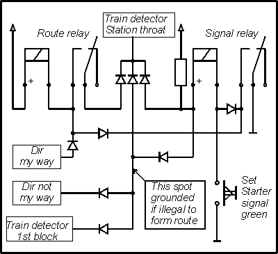
As the train moves past the starter signal, the signal should go red. This happens as the train detector that senses trains between starter and home signal (station throat) will detect the train. This event must not release the device holding the direction wire grounded. If thinking with relays, one should have a separate relay for signal control and another for route control. The route relay should, in this case, stay as energized (provided a energized relay means the route is set, or that the signal is cleared (green)). Only after the train has left the station area (gone past the home signal) should the route relay release.

Generalized idea of the logic at station
From then on, it is the matter of the block control system to keep the correct direction wire grounded in case there is a train within that block. A line block system must have a memory, that will recall the direction of the last train (as in Finland the opposite direction block signals are all red and the signals in favour to the direction of travel are only green (or yellow), in case there is no train immediately ahead (or behind the immediate block).
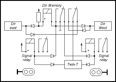
A simple bistabile is enough to keep record of the last grounded direction wire. In case the block becomes occupied the wire memorized as the last direction will be actively grounded by this block.

Generalized idea of the contents of "black box" on single track.
Only in case there are no trains within the blocks between stations, and no-one tries to feed another train to the present directiuon of travel, may the opposite direction wire be grounded by request of sending a train to opposite direction. As this will cause the grounding of the opposite direction wire, all block control systems will change state.
NOTE: This is still pure guessing and theory, not yet fully tested on paper and surely not on layout!
The diagrams display relays. The idea is that the system could be realized with relays or with C-MOS or computers, the design must be flexible enough to allow this! In our case, I'd rather use programmable logic (PIC's) but that should not be the only way!
9095 kävijää/visitors
© 1996-2023 Tapiola Parish Model Railway Club / Tapiolan seurakunnan pienoisrautatiekerho, Viimeksi päivitetty / last modified (none). Created with Notepad.
Text, drawings and photos are protected by copyright laws. Technical solutions, methods and source code are public domain only for non commercial purpose. All development has been carried out during our free time, mainly funded from our own pocket and with non selfish goals, so the use of this material for profitable use (including construction for a friend aginst a fee) is forbidden without written permit from the club. The pages contain errors, so, if you use the data given, you do so at your own risk and responsibility. If you further develop material found on these pages you must put it on display without fee e.g. to a freely available web page. We expect a note about this also.
Pages tested with W3C validator -- didn't look good ;)
[YHTEYSTIEDOT] Älä lähetä sähköpostia!
Tekstit, kuvat ja piirokset ovat tekijänoikeuslain suojaamia. Tekniset ratkaisut, menetelmät ja lähdekoodit ovat vapaasti kopioitavissa ja hyödynnettävissä ei-kaupallisissa tarkoituksissa. Kaikki kehitystyö on tehty vapaa-aikana ja pääosin henkilökohtaisilla varoilla eikä hyötymistarkoituksessa, siksi materiaalin käyttö hyötymistarkoituksiin (sisältäen kaverille rahasta rakentamisen!) on kielletty ilman kerhon kirjallista lupaa! Sivuilla esiintyy virheitä. Jos käytät sivujen tietoja hyväksesi, teet sen täysin omalla vastuullasi. Mikäli kehität sivuilla esiettyjä ajatuksia kytkentäkaavioita tai koodia edelleen, on sinun asetettava se maksutta kaikkien saataville esimerkiksi Internetiin. Odotamme vastavuoroisesti tietoa suoritetusta edelleenkehitystyöstä.
Sivut testattu W3C validatorilla -- ei näyttänyt hyvältä ;)