|
|
From my home workshop:
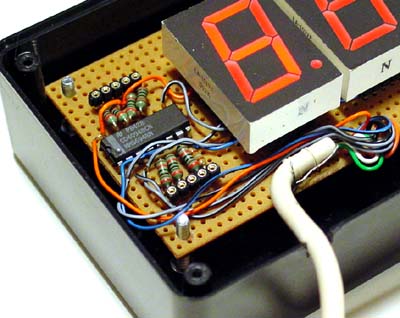
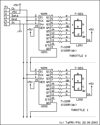
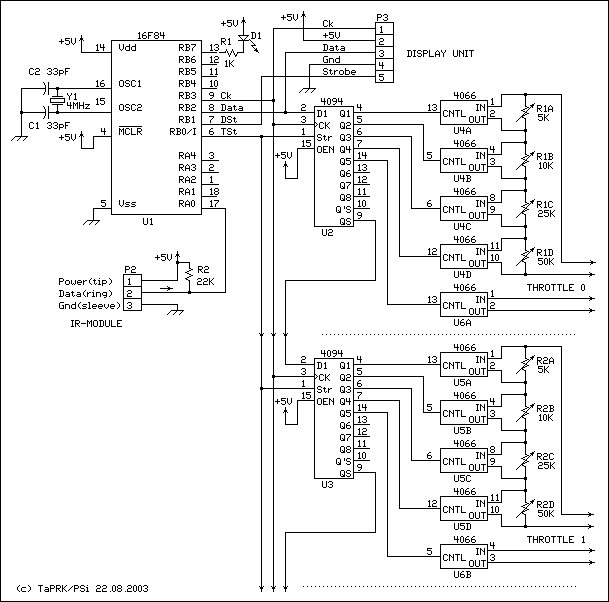
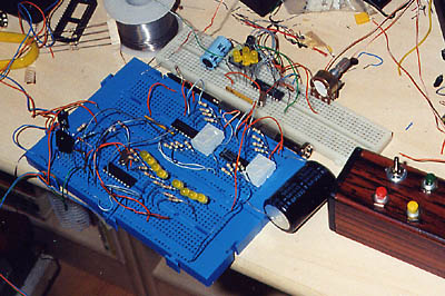
Mk I receiver proto (blue breadboard). Top part of the blue breadboard is the
display unit, lower part the receiver proper (the processor and LED's to mimic
C-MOS switches).
Pot transmitter is on the white breadboard.
Yellow LED's to show speed setting.
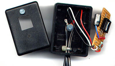
On the right is the finished button transmitter
Mk II
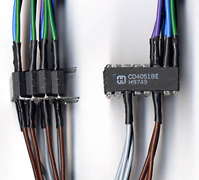
To save space and labour the throttle selector muxes (one set for speed
and one for direction switch) were soldered in piggyback fashion.
This is not yet tested -- and belongs to the series "don't try this at home!".
Top wires (9,10,11) are 8-ch analogue mux channel selectors. The gray (3) is
inhibit that disconnects IR-throttle selected to channel 0. (this is
a bit odd: we get binary ch selection as 0...8 from IR-throttle, and this
needs to be decoded into ihibit + channel 0...7 to represent ch 1...8). Brown
wire (pin 6) goes to speed mux (or direction switch) of the IR-throttle.
stacked connections are the power supply and to replace TMW-DCC's 8
cab speed pots or dir switches.
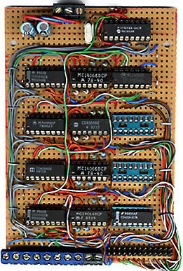
Well -- I got this far (the piggyback chips are not yet fitted), when
I started to think: I have at least three times as much stuff on this card
than the rest of the TMW-DCC setup has. Not such a clever design after all...
Mk III
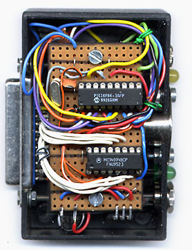
So, I swapped the lot to this:
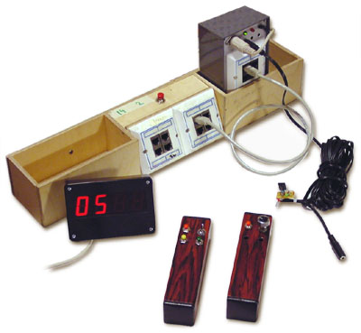
This is the PC-eliminator opened:
On the left is the D-25 connector for TMW-DCC LPT connector, on the right
top the 3.5mm jack for daisy chained IR receivers, yellow LED to show if data is coming,
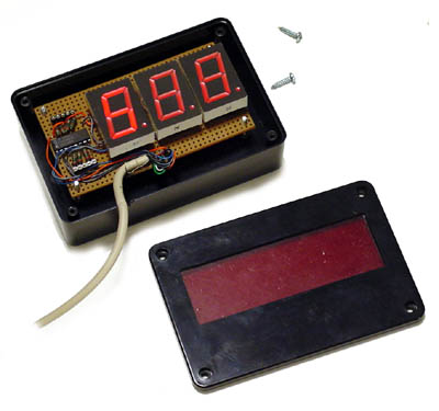
5-pole stereo DIN socket for display unit, green LED to show the system is on
and a 2.5mm dc-adapter connector for power.
The Vero board has PIC16F84 with xtal (and caps on the side), and one latching
shift register for LPT interface, voltage regulator and a capacitor to smoothen up.
The rest is in the software (Bugs!).
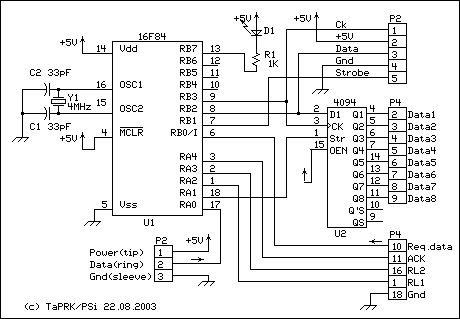
The PC-eliminator schematic.
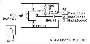
P2 is the IR-module connector,
P3 is for the display unit (same as in MkI/II)
P4 is the LPT-connector D25F. It can be connected directly to TMWDCC
aluminium box with a gender changer or with the D25M-D25M cable that we used
for connecting the TMWDCC aluminium box to PC.
P1 (not drawn) is the power supply. The system uses a battery eliminator,
rectifier, 1000uF/25V electrolytic capacitor and a 7805 three terminal regulator
for power supply (not drawn).
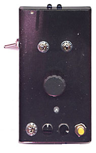
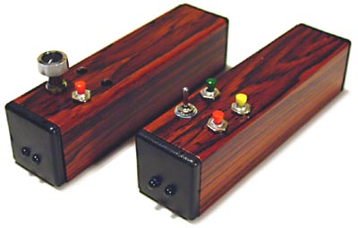
The throttle top view
Top switches are for F0/FL and F1, direction is on the side, pot for speed and at the
bottom is the 14/28 speed step selector, loco address selectors (1..99) and
button to activate the channel selection
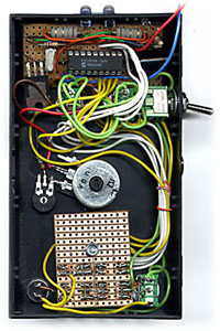
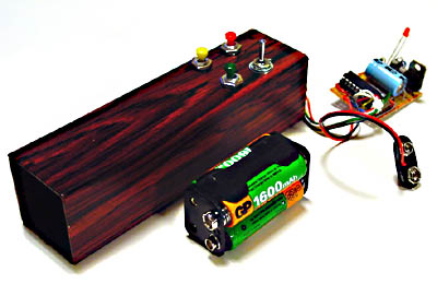
Inside the throttle
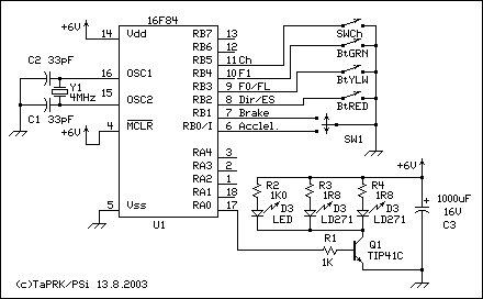
The Vero board: Top are the IR-leds (LD271) and their resistors (1R8), then the IR led driver
transistor (TIP41), 4.000 MHz crystal w. 33pF caps, the PIC16F83 processor
and 1000uF electrolytic capacitor to support the IR LED's huge drain.
In the middle: the 1M pot, 100K trimmer and 10K resistor to adjust the pot zero
point.
At the bottom: the 14/28 step switch, BCD-switches and address activating button.
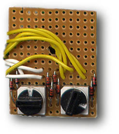
BCD-switches and diodes. Note that one of the yellow wires has been squeesed
while the unit was fitted.
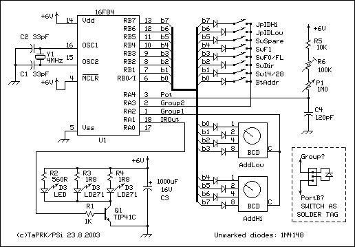
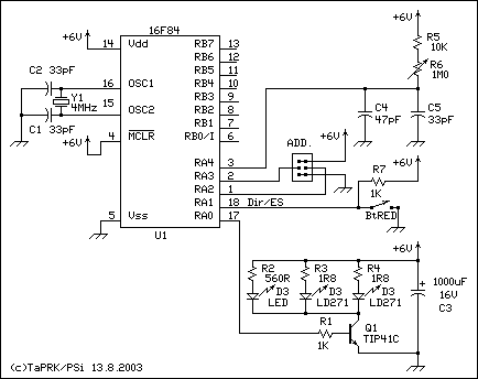
Mk III potentiometer transmitter schematic.
The 6V power supply is from 4 AA battery cells. The schematic also shows how
the diodes were soldered to switch terminals.
13869 kävijää/visitors
© 1996-2023 Tapiola Parish Model Railway Club / Tapiolan seurakunnan pienoisrautatiekerho,
Viimeksi päivitetty / last modified (none). Created with Notepad.
[CONTACT INFO] Don't send e-mail!
Text, drawings and photos are protected by copyright laws. Technical
solutions, methods and source code are public domain only for non commercial
purpose.
All development has been carried out during our free time, mainly funded
from our own pocket and with non selfish goals, so the use of this material
for profitable use (including construction for a friend aginst a fee) is forbidden
without written permit from the club. The pages contain errors, so, if you
use the data given, you do so at your own risk and responsibility. If you
further develop material found on these pages you must put it on
display without fee e.g. to a freely available web page. We expect a
note about this also.
Pages tested with W3C validator -- didn't look good ;)
[YHTEYSTIEDOT] Älä lähetä sähköpostia!
Tekstit, kuvat ja piirokset ovat tekijänoikeuslain suojaamia.
Tekniset ratkaisut, menetelmät ja lähdekoodit ovat vapaasti kopioitavissa
ja hyödynnettävissä ei-kaupallisissa tarkoituksissa. Kaikki kehitystyö on
tehty vapaa-aikana ja pääosin henkilökohtaisilla varoilla eikä hyötymistarkoituksessa,
siksi materiaalin käyttö hyötymistarkoituksiin (sisältäen kaverille rahasta
rakentamisen!) on kielletty ilman kerhon kirjallista lupaa! Sivuilla esiintyy
virheitä. Jos käytät sivujen tietoja hyväksesi, teet sen täysin omalla vastuullasi.
Mikäli kehität sivuilla esiettyjä ajatuksia kytkentäkaavioita tai koodia
edelleen, on sinun asetettava se maksutta kaikkien saataville esimerkiksi Internetiin.
Odotamme vastavuoroisesti tietoa suoritetusta edelleenkehitystyöstä.
Sivut testattu W3C validatorilla -- ei näyttänyt hyvältä ;)
|
