TaPRK
General
Projects
Shows
Excursions
Links
Yleistä
Ratoja
Projektit
Näyttelyt
Retket
Linkit
Parish/SRK
Tapiola Parish Model Railway ClubKauniainen, electrification |
|---|
Considering the electrification in frame construction
As the distance from subroadbed top to bottom of blue foam is 90 mm (3 3/5 ") it was decided that the turnout motors will be fitted into "wells" cut into blue foam. The wells were drilled to lower foam boards with a tool that is used to make flush installations of wall outlets etc. (What's the name of the tool?)To make interconnections from well to well the lowest board had channels cut into it with home made hot wire carving tool (soldering gun with thick steel wire loop replacing the original bit). To get track feeders through the roadbed we used 3mm (1/8 in) drill and a knittig needle. For feeder wires we did shallower wells i.e. we only cut the bottom foam board. The turnouts had two boards cut.
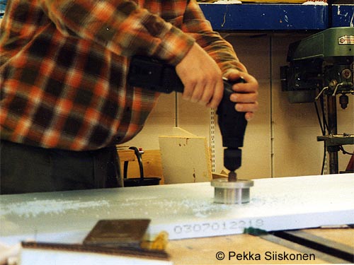
It was easy to cut wells with this tool (BTW: the table is still intact -- the centre bit goes between two tables and the board was moved before the drill went through ;)
The bottom side of the sub roadbwd is where the point motors will be fixed.
After drilling the wells and glueing the boards together a piece of 3mm (1/8 in) polystyrene
was glued to the bottom of the well and the motors fitted with 3mm woodscrews.
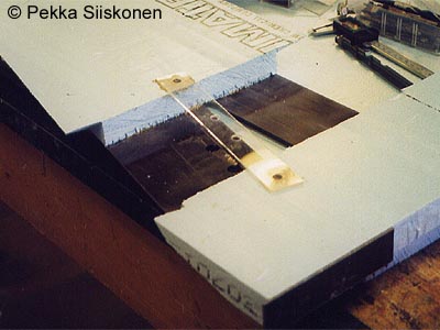
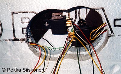
The underpass had to house two point motors: The motors are attached to clear plastic board
glued and screwed to subroadbed. The motors will be somewhat disguished with lorries
and buses placed inside the undepass.
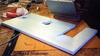
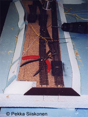
Here are the wells of the rest of the west end station module. Also visible is is the Tunnelitie underpass and small cuts for the point motor fixture.
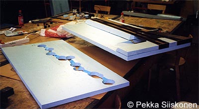
The lowest board has both turnout wells and feeder wells and the channels cut to join the wells.
The point motors fitted to styrene board pieces with woodscrew.
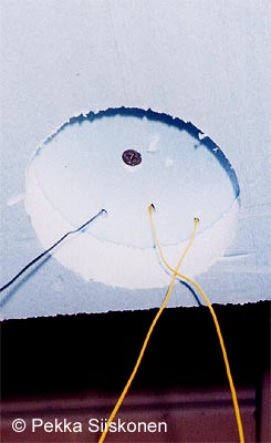
the holes for feeders were first drilled through the cork and the pressed with knitting needle, aiming to the feeder wells, and connected through the wiring channels and tied together
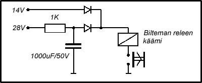
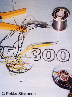
Modified car relays haven't got enough force to move the Tillig turnouts so we needed a kick-start circuit to every point motor: The motor gets a 28 volt kick but will be held in position with 14 volts.
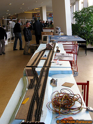
Turnouts were operated from temporary panels at each end of the yard.
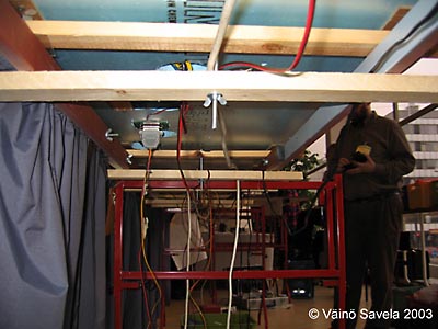
The station modules were temporarily fitted with 25 pin D-connectors for power supply. The connectors will be moved to cross members for rigdness.
Time to think: We have most of the trackwork electrified. The car relay wasn't a good choice for Tillig turnouts. We also needed repeater relays as the motors are not returning fully back to release position (Tillig turnouts have no hinges at points!)
The wiring channels should be in the underside of the middle board as it has less to do in respect of strength of the module.
Signalling and final turnout control is not yet finalised. At the moment we are investigating different train detector types.
5510 kävijää/visitors
© 1996-2026 Tapiola Parish Model Railway Club / Tapiolan seurakunnan pienoisrautatiekerho, Viimeksi päivitetty / last modified (none). Created with Notepad.
Text, drawings and photos are protected by copyright laws. Technical solutions, methods and source code are public domain only for non commercial purpose. All development has been carried out during our free time, mainly funded from our own pocket and with non selfish goals, so the use of this material for profitable use (including construction for a friend aginst a fee) is forbidden without written permit from the club. The pages contain errors, so, if you use the data given, you do so at your own risk and responsibility. If you further develop material found on these pages you must put it on display without fee e.g. to a freely available web page. We expect a note about this also.
Pages tested with W3C validator -- didn't look good ;)
[YHTEYSTIEDOT] Älä lähetä sähköpostia!
Tekstit, kuvat ja piirokset ovat tekijänoikeuslain suojaamia. Tekniset ratkaisut, menetelmät ja lähdekoodit ovat vapaasti kopioitavissa ja hyödynnettävissä ei-kaupallisissa tarkoituksissa. Kaikki kehitystyö on tehty vapaa-aikana ja pääosin henkilökohtaisilla varoilla eikä hyötymistarkoituksessa, siksi materiaalin käyttö hyötymistarkoituksiin (sisältäen kaverille rahasta rakentamisen!) on kielletty ilman kerhon kirjallista lupaa! Sivuilla esiintyy virheitä. Jos käytät sivujen tietoja hyväksesi, teet sen täysin omalla vastuullasi. Mikäli kehität sivuilla esiettyjä ajatuksia kytkentäkaavioita tai koodia edelleen, on sinun asetettava se maksutta kaikkien saataville esimerkiksi Internetiin. Odotamme vastavuoroisesti tietoa suoritetusta edelleenkehitystyöstä.
Sivut testattu W3C validatorilla -- ei näyttänyt hyvältä ;)