TaPRK
General
Projects
Shows
Excursions
Links
Yleistä
Ratoja
Projektit
Näyttelyt
Retket
Linkit
Parish/SRK
Tapiola Parish Model Railway ClubTurntable |
|---|
Masa built the "Truman", or Tr2 class "Russian decapod" on Piko underframe, using plastics. After finishing that project he was ready to try underframe construction, to build a Hv3 loco.
I (Pekka) told him, that I first want him to build the locomotive depot, and then go into loco scratchbuilding. Hence he has been building the turntable for the depot.
Photos on this page are courtesy Opa, Antti, Olli and Pekka
|
|
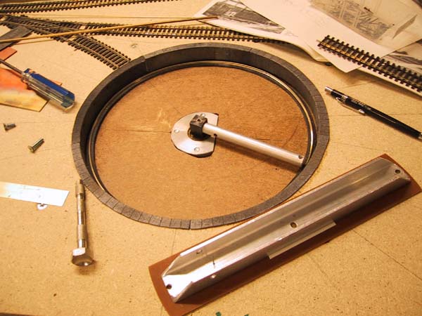
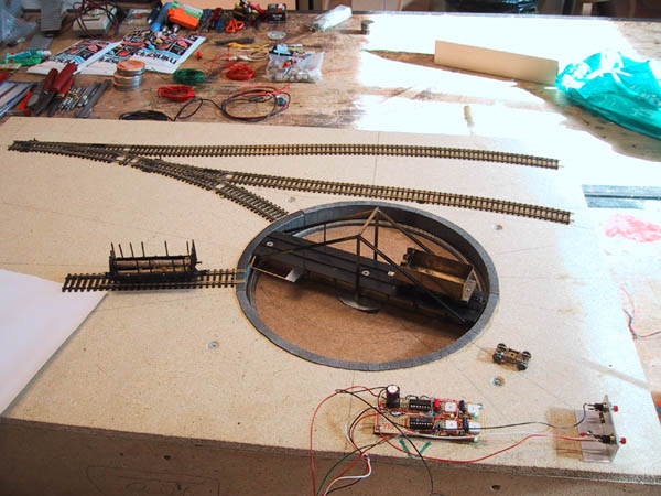
The mechanical construction of the table is a design of Mr Koskela: ex. 1/2 in. HP tape drive unit's tension arm assembly acts as the load bearing unit. The arm has two tapped holes drilled, and inverted U-channel aluminium profile is attached to it in order to form the solid base for the turntable bridge. The turntable pit is a separate plywood sheet and the bearing unit is attached to this. The plywood is then fixed to the layout base with long screws having nyloc nuts as stoppers and wing nuts for fixing. This way we can adjust the vertical plane of the turntable to match the layout. Ring rail is only cosmetic, but it will later act as feeder to the track on the bridge. The pit edges are fixed to the layout cover and the joint between pit bottom edge and plywood bottom of the pit is concealed befind ring rail base. The pit edge does not reach to the bottom to allow for adjustments. |

|
|
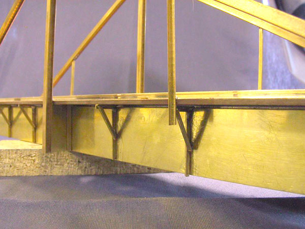
The bridge top is PCB, glued on top of the aluminium U-channel, and the rails are electrically separated with a jagged insulation made with a minidrill. The line is jagged to prevent bending. The superstructure is brass, soldered together and soldered to the PCB, and later insulated from one side. |
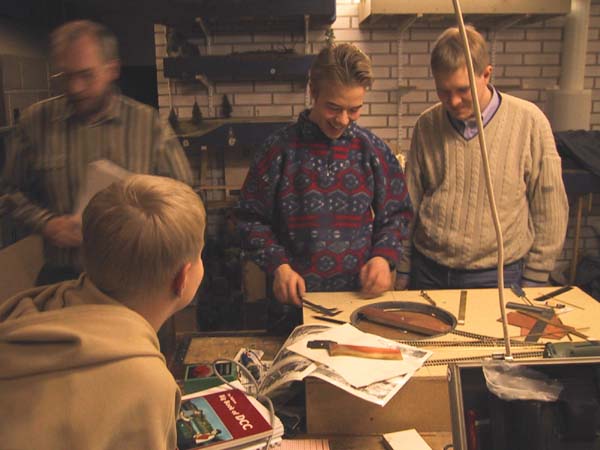
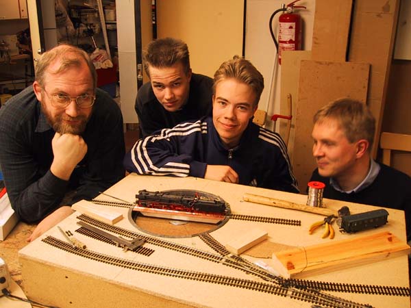

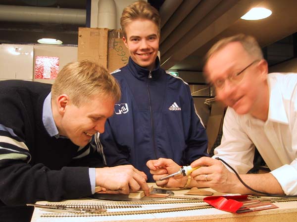
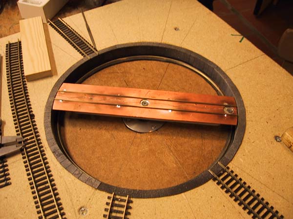
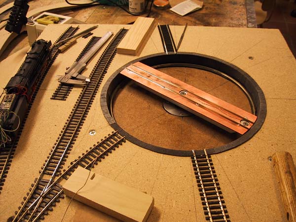
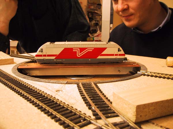
 Table.jpg Table.jpg
|
As the aluminium U-channel was not dead center (I drilled the holes!), the
cosmetic side members (brass) were packed to make the outside look symmetrical.
The details are glued on, except the cabin base, which is soldered together.
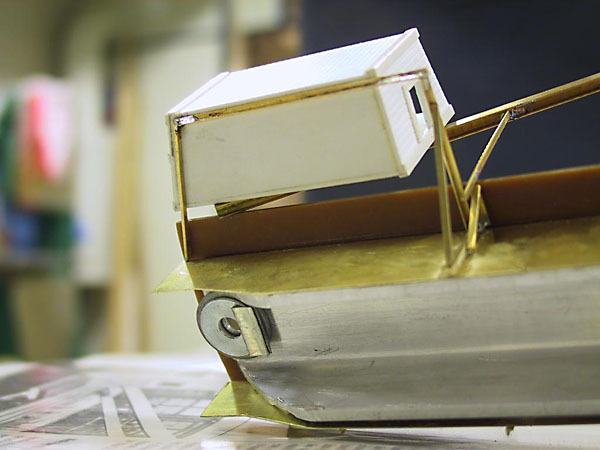
The cabin is made of scribed polystyrene. |
 ttmotor_1.jpg ttmotor_1.jpg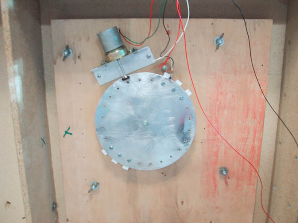 ttmotor_2.jpg ttmotor_2.jpg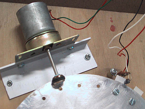 ttmotor_3.jpg ttmotor_3.jpg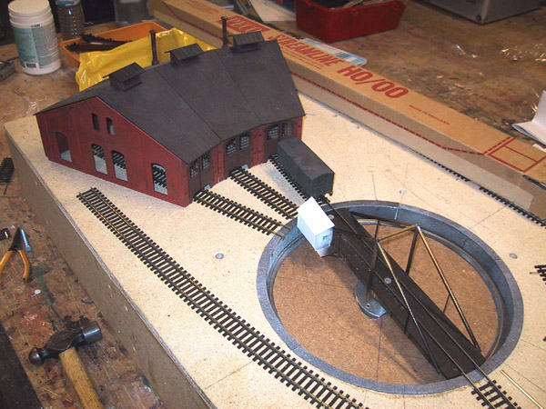 kpoyta.jpg kpoyta.jpg ttbottom.jpg ttbottom.jpg
|
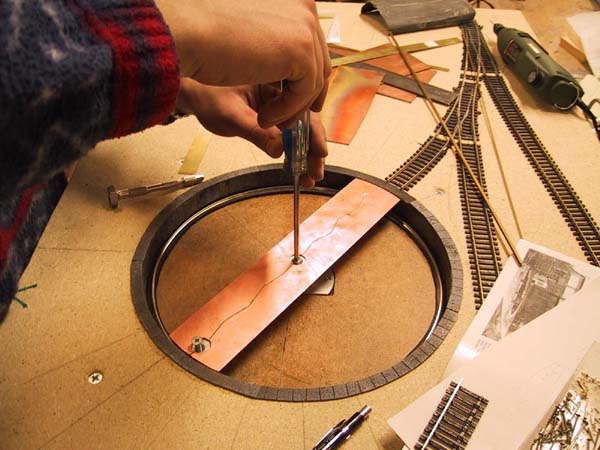
Below the baseboard we have a largish aluminium plate fitted to the axle (there was a screw conveniently at the axle centre). The aluminium plate has a friction drive system to operate the bridge. Microswitches will be fixed to turn the polarity of the bridge tracks (we aim to have the layout built with reliability in mind -- if we loose aux. power we can still run over the bridge and turn it manually as there will be no electronics in track polarity system). The bridge's electronic indexing was tested for the first time on Sunday 9th July 2001 The idea is based on Teton Line's turntable indexing, but we use only one opto-sensor pair and detect only the other edge of the "vane". 
Opto-sensors are usually used to detect if the beam of light is blocked or not. We instead search for the "gray area" in between. The system basically has a window discriminator where one op-amp detects if the beam is blocked, and the other if the beam is un-blocked. On both cases the amount of darkenss required is adustable, so that we also have a situation, where the beam is not blocked and not un-blocked. In this situation the table has reached the correct position. The other op-amp will drive the table clockwise and the other anti-clockwise. Additional electronics provide for slow acceleration of the table, so that whenever the correct position is found, the table will be almost instantly halted but it allways overshoots, so the electronics will slowly accelerate the table again towards the correct position. As the table is stopped from slower speed than before, the table will halt closer and closer to the correct spot and thus due to slow acceleration will not gain speed to pass the correct spot as fast and far as at the previous attempt the table will eventually (after approx. three trials) find the correct spot. 
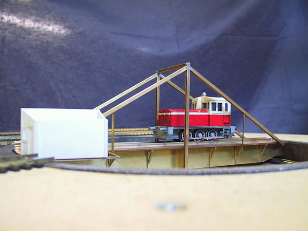
I wished to separate the window position setting from the window size setting. On the right is a suggestion from Model Electronics Railway Group MERG to make the adjustment easier. The turntable was shown to public at the Helsinki Club's Xmas exhibition 2001. We added a pin to the aluminium plate that operated a microswitch that changed the track polarity of the table via a relay. The table also has a motorcycle dynamo carbon for current pickup from the ring rail, the other polarity comes via the axle. The positioning system worked well, it was fun to see the audience reactions when the table halted not quite correctly, but after a brief moment then shifted a bit to actually align the rails. The positioning system and pickup will be developed further. |
Surprisingly identical approach done long before ours -- I understand -- at MIT Model Railroad Club
21199 kävijää/visitors
© 1996-2026 Tapiola Parish Model Railway Club / Tapiolan seurakunnan pienoisrautatiekerho, Viimeksi päivitetty / last modified (none). Created with Notepad.
Text, drawings and photos are protected by copyright laws. Technical solutions, methods and source code are public domain only for non commercial purpose. All development has been carried out during our free time, mainly funded from our own pocket and with non selfish goals, so the use of this material for profitable use (including construction for a friend aginst a fee) is forbidden without written permit from the club. The pages contain errors, so, if you use the data given, you do so at your own risk and responsibility. If you further develop material found on these pages you must put it on display without fee e.g. to a freely available web page. We expect a note about this also.
Pages tested with W3C validator -- didn't look good ;)
[YHTEYSTIEDOT] Älä lähetä sähköpostia!
Tekstit, kuvat ja piirokset ovat tekijänoikeuslain suojaamia. Tekniset ratkaisut, menetelmät ja lähdekoodit ovat vapaasti kopioitavissa ja hyödynnettävissä ei-kaupallisissa tarkoituksissa. Kaikki kehitystyö on tehty vapaa-aikana ja pääosin henkilökohtaisilla varoilla eikä hyötymistarkoituksessa, siksi materiaalin käyttö hyötymistarkoituksiin (sisältäen kaverille rahasta rakentamisen!) on kielletty ilman kerhon kirjallista lupaa! Sivuilla esiintyy virheitä. Jos käytät sivujen tietoja hyväksesi, teet sen täysin omalla vastuullasi. Mikäli kehität sivuilla esiettyjä ajatuksia kytkentäkaavioita tai koodia edelleen, on sinun asetettava se maksutta kaikkien saataville esimerkiksi Internetiin. Odotamme vastavuoroisesti tietoa suoritetusta edelleenkehitystyöstä.
Sivut testattu W3C validatorilla -- ei näyttänyt hyvältä ;)