Construction Methods
Construction methods are intentionally kept simple. The baseboard/framework
is assembled from pre-cut chipboard using white glue and screws.
Track is laid from flexible track elements that are nailed on the chipboard roadbed.
Scenery is supported by chicken-wire stabled to the baseboard.
Paper towels are torn to pieces, diluted in plaster
and laminated over the chicken wire. Basic vegetation is made of dyed sawdust
and ground foam (ground with a hand operated meat grinder!). Tree trunks are
made of steel wire, or cable, main foliage of steel wool covered with dyed
ground foam.
The trackwork is ballasted using real sand (dirt) and glued with diluted
white glue with a drop of washing-up-liquid to reduce surface tension.
Bridges and buildings are made from plasticard (polystyrene) or by converting commercial
kits to suit.
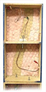
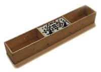
The left hand picture shows the underside of a short 60 cm front-back
transition module. Clearly visible is the chipboard frame and roadbed, chicken wire
support for scenery and the underside of the plaster hard cell scenery. The cable is
for track power and it has RCA phone connectors at each end. During transit the connectors
are fixed with clothespins that are glued underneath the baseboard.
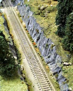
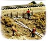
The right hand picture shows a rock cutting. Here we used
expanded polystyrene (styrofoam). The foam slabs were formed with hot wire cutter and then
covered with plaster, and the sharp edges of rock face of the cutting were finished after
the plaster had settled. The rock is painted with latex and "finger paint" colours:
We had an open plastic box with black, white red and blue paint in each corner
and the paint was mixed with the paintbrush to create all kinds of different
shades of dark granite.
The basic vegetation is formed by liberally painting the plaster
surface with earth or green colour and dyed sawdust was then sprinkled over the wet paint
and secured with spray of diluted white glue. Spuces are made from bits of
untwisted manilla rope and soft wire twisted with a hand drill, pines are made of pieces
of (lichen-like) washing sponge and soft wire and birches from steel wool and soft wire.
The trees were then finished with a spray of latex paint and dyed ground foam (home made or
Woodland Scenics).
Electrics
Electrification is quite time consuming. Electrification of a modular layout
is easy, as the modules can be set on table and work done without kneeling
underneath the layout and getting hot solder all over your face ;-)
Olli (one of our
members) is installing some digital command control connectors under the
module.
A basic connection of a dc throttle.
We used hand held walk-around dc controllers/throttles. This enabled the operators
to stay closer to the moving trains especially during shunting/switching. The
controllers/throttles were powered using inexpensive car/automotive battery chargers.
As those are capable of delivering currents over 4 ampere, electronic current
limiter in the controller/throttle is essential!
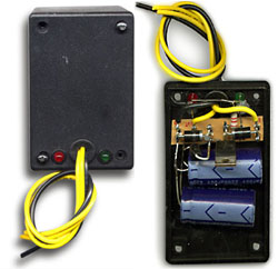
Capacitor Discharge Unit (with charging and discharging LED's).
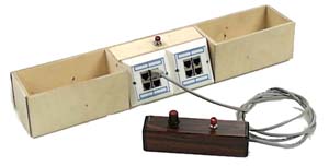
Control panels
Turnouts and signals are controlled from control panels (left) attached
to the side of the layout. The panels have push buttons for turnout control and
levers for setting the signals at each end. The layout wiring is designed for dc operation and around
power routing turnouts, so that the need for sectional switches is minimal.
If a train is to depart, and the layout is operated with dc, the signal switch is turned away from the station and this
will disconnect the yard end from the local controller/throttle and connect the yard
end to the line between stations. If a train is to arrive, the signal switch is turned
towards the yard, and thus the line will be connected to local controller/throttle
and the station operator here can take the train from the next station to this station.
If no trains are to depart or arrive, the signal switches are kept at centre, and the
local controller/throttle is connected to yard. The turnouts may be thrown only
if the signal switches are a centre position. With the command control the need for
connecting and disconnecting of sections and controllers/throttles has gone, but in
case of breakdown we can easily convert to "old fashioned" dc control.
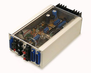
Power supply
The power source for auxiliary devices (lights, relays and point
motors) was taken from a centralized power unit. The unit contained half wave
rectifier and huge capacitor for 15 vdc aux. power and a voltage doubler to feed
the capacitor discharge system also housed in the same
case. We have now abandoned the centralized CDU and installed local CDUs to all control panels.
In 2002 we abandoned the central power source and instead fitted all stations with independent
power source and panel mounted CDUs (picture on the right).
We have plans of converting the control panels to use RS-485 bus. This way we would be able to reduce
the cables between panel and layout and prepare for future plans of centralized traffic
control (CTC). This way the stations would no longer be manned, and the local panels are then
only to be used for shunting/switching by the train driver.
The Digital Command Control
The club now has a command control system to operate trains in more
realistic manner. With command control the layout does not need to be sectionalised
to gain individual control of locos, all the commands needed to control the locos are sent
through the rails and locos have special receivers, or decoders that can interpretate
the commands that are intended for this particular loco.
American Model Railroad Association -- NMRA
has standardized the commands that are sent through the rails, so by adhering to
NMRA
Digital Command Control Standards one is not tied to a single manufacturer.
The heart of the system at Tapiola is a do-it-yourself central unit
built around used PC-computer. Controllers/throttles (right hand picture) are connected
to the computer's joystick port and the layout booster (left) to the parallel port.
The software and schematics to build this system are from the Internet.
The system -- TMW-DCC -- is designed by Mr Lars Lundgren
from Sweden. We have kept a diary about the
costruction of the Tapiola system.
The PC is no longer used at exhibitions, as the "PC-eliminator" and Infrared remote controllers have
taken it's place!
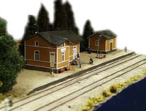
Stations
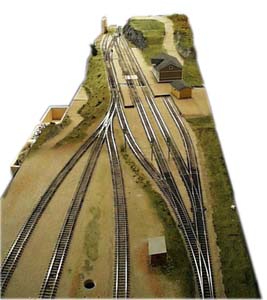
We build our stations from two sections, always used as a pair and thus forming
a two-part module.
Station yards are intentionally kept quite small, but are aimed to be
somewhat challenging for switching. The yards only have two or three through tracks
and some spurs.
Our largest station is quite unfinished. It's 60 cm wide
and 240 cm long. The station will also have a separate loco depot, and it extends
the station area to 450 cm The turntable project is featured at our
projects page. The unfinished depot was displayed
at Helsinki Model Railway Club's Xmas exhibition 2001 and at Model-Expo 2002 -exhibition.
Club Evenings
The layout is still far from finished, so there's plenty to do to any local
over 12-year-old. We have set the age limit as more time is spent
in construction than driving, so patience is required. We also use power tools which
may turn out to be potentially hazardous to children of younger age.
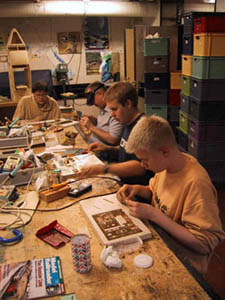
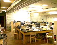
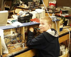
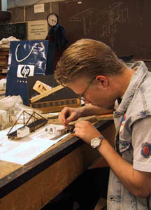
Our members are also building rolling stock from etched brass kits.
On right hand picture Mikko, Kari, Opa and Olli are building Hr1 and Vv13 class locos.
On left hand photo Masa builds the turntable and Hv4 class steam locomotive (scratch built).
15177 kävijää/visitors
© 1996-2026 Tapiola Parish Model Railway Club / Tapiolan seurakunnan pienoisrautatiekerho,
Viimeksi päivitetty / last modified (none). Created with Notepad.
[CONTACT INFO] Don't send e-mail!
Text, drawings and photos are protected by copyright laws. Technical
solutions, methods and source code are public domain only for non commercial
purpose.
All development has been carried out during our free time, mainly funded
from our own pocket and with non selfish goals, so the use of this material
for profitable use (including construction for a friend aginst a fee) is forbidden
without written permit from the club. The pages contain errors, so, if you
use the data given, you do so at your own risk and responsibility. If you
further develop material found on these pages you must put it on
display without fee e.g. to a freely available web page. We expect a
note about this also.
Pages tested with W3C validator -- didn't look good ;)
[YHTEYSTIEDOT] Älä lähetä sähköpostia!
Tekstit, kuvat ja piirokset ovat tekijänoikeuslain suojaamia.
Tekniset ratkaisut, menetelmät ja lähdekoodit ovat vapaasti kopioitavissa
ja hyödynnettävissä ei-kaupallisissa tarkoituksissa. Kaikki kehitystyö on
tehty vapaa-aikana ja pääosin henkilökohtaisilla varoilla eikä hyötymistarkoituksessa,
siksi materiaalin käyttö hyötymistarkoituksiin (sisältäen kaverille rahasta
rakentamisen!) on kielletty ilman kerhon kirjallista lupaa! Sivuilla esiintyy
virheitä. Jos käytät sivujen tietoja hyväksesi, teet sen täysin omalla vastuullasi.
Mikäli kehität sivuilla esiettyjä ajatuksia kytkentäkaavioita tai koodia
edelleen, on sinun asetettava se maksutta kaikkien saataville esimerkiksi Internetiin.
Odotamme vastavuoroisesti tietoa suoritetusta edelleenkehitystyöstä.
Sivut testattu W3C validatorilla -- ei näyttänyt hyvältä ;)
|