TaPRK

 General
 Projects
 Shows
 Excursions
 Links

 Yleistä
 Ratoja
 Projektit
 Näyttelyt
 Retket
 Linkit

 Parish/SRK

Tapiola Parish Model Railway Club


IR-throttle project


This is a PC replacement project using TMW-DCC hardware and additional logic and IR throttles to replace the PC and joystick connected throttles. The proto is now working, and is featured here. Note: this has no programming features and will only contain mechanism to deliver baseline packets and Group 1 function packets (F0/FL..F4).

For better functionality and more features, stick with TMW-DCC using PC — and wait for the TMWDCC2 ;)


The data below is about all three versions, see readme.txt for details! The two previous ones (Mk I and Mk II) are not going to be developed further and will stay as partly working protos!
All source code is PD for non profit use only and only if the further developed source code is made freely available and public also!

Note: The Mk III version receiver (PC-eliminator) code has had a stack overflow error which has partly affected in the unreliable behaviour (locos loosing control, but regained after pressing address select button at transmitter). Version C has the code fixed.


Readme.txt
Some background information about IR remote control design and short description about the prorgess made (covers all three versions)
Images
Some images of the project components (all three versions)
links.txt
Links related to this project (all versions)

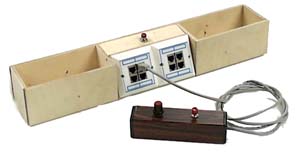
Original TMWDCC control


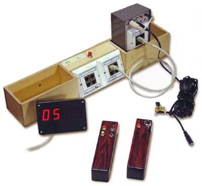
The controllers were connected to PC's joystick card and the PC's parallel port delivered NMRA-DCC data in 8-bit parallel form. Locos were assigned with keyboard commands to these controllers. With addition of another joystick card there were sockets for 8 controllers (we used four controllers and changed locos by changing the socket where the controller was plugged in. The TMWDCC hardware converted the 5-volt 8-bit parallel data into 14 volt serial square-wave NMRA-DCC signal.

1st version: Joystick replacement controllers


The original IR-system replaced the throttles connected to joystick card. The cmos switches operated the resistor network and pressed the button. The IR receiver resistor networks were connected with interchangeable patch cables to controller sockets, thus replacing wired controllers potentiometer and dir. button

The prototype throttles are presently on loan to Mr T.S.Knutsen of Drammen, Norway since August 2003 for testing in Høæstmesse in Oslo in September 2003.

receiver.asm
Receiver source code. This controlled the shift registers operating speed control muxes and 7-segment display unit. Functions not working!
receiver.gif Schematic of the receiver
tsop1738.gif Schematic of the IR receiver modules
tx_butt.asm
Button transmitter. This started as Lorel Joiner type of throttle but has now been changed so that it sends actual speed step instead of "faster" or "slower" command. Function buttons not working!
tx_butt.gif Schematic of the button transmitter
tx_pot.asm
Potentiometer transmitter. This has the pot connected in much the same way as the PC joystick is connected within PC joystick port. Only 4 bit resolution. Direction OK, functions never finished...

1B version: Joystick replacement controllers w. functions to button version

rec_1B.zip
Receiver project (asm, hex etc).
tx_butt2.zip
Button transmitter project (asm, hex etc) (F1 and FL/F5)
tx_pot_1.zip
Potentiometer project (asm, hex etc) (no functions)

2nd version: Joystick replacement controllers w. throttle selector (totally unfinished!)


The cmos crosspoint choose the socket to which the resistor network (that replaces the original controllers pot) were plugged in.

receiver.asm
Dev. version w. cab channel selection (four IR-throttles, 8 possible channels (channel meaning cab plug!). Only cab 0 had all the functionalities, as the code was not originally made modular. This was never finished, the software only operates the display as hardware was never completed!
tx_butt.asm
2nd version included cab channel selection (four IR-throttles, 8 possible channels)
Pot version
Never done!

3rd (present) version: PC replacement (PC-eliminator)


The cmos crosspoint became so clumsy, so the whole desing was re-planned! The IR receiver processor will now deliver the 8-bit parallel data directly to TMWDCC hardware. The design makes the IR receiver processor less time critical than letting it do all the work! The controllers can now choose the loco they will operate!

dcc_cmd.asm
PC-eliminator source code. This now controls the TMW-DCC hardware and original display unit.
tx_pot_2.asm
Potentiometer transmitter.
The source codes are not final! There are no proper schematics or detailed descriptions about the parts of this project yet, as this is still evolving, but those familiar with PIC processors may get something out of my coding (a good laugh -- perhaps!)
All in all the Mk I setup did work during three day Model-Expo 2002!
We have since Model-Expo 2002 used solely the Mk III system in exhibitions. It has some problems (needs pressing the address selector button from time to time).
tx_pot3b.asm
Proto transmitter with functions FL..F4. Throttle ID hard-coded (this is sample Throttle 2 (of 1...4). It has toggle switches for F0...F2 and "mom-off-mom" switch for F3 and F4 Short throw will toggle, long throw will activate function for the duration of throw. Built to get most out of Antti's Roco Nohab w. sound! The schematic is slightly different (apparent by looking the asm file)!
Turku Exhibition and Helsinki MRC's Xmas show 2003 were run with this unit!
Future enhancements will bring rotary encoders instead of potentiometers or at least reversal of potentiometer interpretation (now larger resistance means higher speed, so worn out pot caused trains charging!)
dcc_cmdc.asm [stack overflow fixed!]
Proto PC-eliminator source code. Better protection aginst stealing locos by insisting that the loco to be stolen must have speed set to zero and that the throttle about to steal is also set to zero speed. After one second of lack of IR messages will start to poll on display the addresses, speed and function settings of all four throttles.
Attention!: Turku Exhibition and Helsinki MRC's Xmas show 2003 were run with B version (i.e. prior stack overflow error fixing)! Version C not tested yet!

tx_pot3i.asm
Simple pot. throttle w. FL and F1, now the pot inverted!
tx_pot4i.asm
Simple pot. throttle w. FL and F1, now the pot inverted, and emg. stop applied if speed reduced very quickly.
tx_pot3bi.asm
Pot. throttle w. FL and F1, F2, F3 and F4, now the pot inverted! No emg. brakes!

dcc_cmd8.asm
PC-eliminator modified for 8 throttles, some bugs fixed [ver. 2007-02-24]
tx_pot4i8.asm
Simple pot. throttle w. FL and F1, now the pot inverted, and emg. stop applied if speed reduced very quickly. Modified for 8 throttles (added one bit to CAB_ID). Cab ID is jumper selected, here MSB is hardcoded zero!
tx_pot3bi8.asm
Pot. throttle w. FL and F1, F2, F3 and F4, now the pot inverted! No emg. brakes! Modified for 8 throttles (added one bit to CAB_ID). Cab ID hard coded to 2 (b001)
tx_enc_8.asm
Encoder throttle w. FL and F1, F2, F3 and F4, No potentiometer, encoder used instead! No emg. brakes! Modified for 8 throttles (added one bit to CAB_ID). Cab ID hard coded [ver. 2007-02-24]
tx_enc_8a.asm
Encoder throttle w. FL and F1, F2, F3 and F4, No potentiometer, encoder used instead! Emg. brakes if direction changed with speed off-zero. Will now send zero speed packets if encoder turned CCV from zero! [ver. 2007-11-18]
tx_enc_8bee.asm
Encoder throttle w. FL and F1, F2, F3 and F4, No potentiometer, encoder used instead! WIRED throttle, reads speed from EEPROM! Emg. brakes if direction changed with speed off-zero. Will now send zero speed packets if encoder turned CCV from zero! [ver. 2008-04-22]

26710 kävijää/visitors
© 1996-2023 Tapiola Parish Model Railway Club / Tapiolan seurakunnan pienoisrautatiekerho, Viimeksi päivitetty / last modified (none). Created with Notepad.

[CONTACT INFO] Don't send e-mail!
Text, drawings and photos are protected by copyright laws. Technical solutions, methods and source code are public domain only for non commercial purpose. All development has been carried out during our free time, mainly funded from our own pocket and with non selfish goals, so the use of this material for profitable use (including construction for a friend aginst a fee) is forbidden without written permit from the club. The pages contain errors, so, if you use the data given, you do so at your own risk and responsibility. If you further develop material found on these pages you must put it on display without fee e.g. to a freely available web page. We expect a note about this also.
Pages tested with W3C validator -- didn't look good ;)

[YHTEYSTIEDOT] Älä lähetä sähköpostia!
Tekstit, kuvat ja piirokset ovat tekijänoikeuslain suojaamia. Tekniset ratkaisut, menetelmät ja lähdekoodit ovat vapaasti kopioitavissa ja hyödynnettävissä ei-kaupallisissa tarkoituksissa. Kaikki kehitystyö on tehty vapaa-aikana ja pääosin henkilökohtaisilla varoilla eikä hyötymistarkoituksessa, siksi materiaalin käyttö hyötymistarkoituksiin (sisältäen kaverille rahasta rakentamisen!) on kielletty ilman kerhon kirjallista lupaa! Sivuilla esiintyy virheitä. Jos käytät sivujen tietoja hyväksesi, teet sen täysin omalla vastuullasi. Mikäli kehität sivuilla esiettyjä ajatuksia kytkentäkaavioita tai koodia edelleen, on sinun asetettava se maksutta kaikkien saataville esimerkiksi Internetiin. Odotamme vastavuoroisesti tietoa suoritetusta edelleenkehitystyöstä.
Sivut testattu W3C validatorilla -- ei näyttänyt hyvältä ;)