|
TaPRK General Projects Shows Excursions Links Yleistä Ratoja Projektit Näyttelyt Retket Linkit Parish/SRK |
This project is not strictly speaking Tapiola club project but I think I can display it in here as it was an interesting one
Why to build an Accessory EncoderThe Helsinki MRC uses Lenz DCC system for turnout control. The system comprises of LZ100 central unit, LV100 booster, LW100 "Tower Cab" turnout button unit and two LW120 control panel interface units.Just two weeks before the layout was to sail to Intermodellbau '03 in Dortmund, the system developed a fault (another of the LW120 boards became dead). There was not enough time to get spare units as none of the Finnish retailers stock this component, so the equipment was sent over to Lenz for repair. Lenz has been a very good supplier and promised to act promptly. As time was getting short, I was asked for a workaround in case the spares would not reach Finland on time. (The repaired unit came week after the Intermodellbau '03, but there was no charge!) Of course the Helsinki club could have used the TV remote like LH100 manual interface or the LW100 tower cab, but the remote is too complicated to use and manage in exhibition, and tower cab was not a very handy interface either. The first remedy was the Tapiola club's TMWDCC system. We programmed one portable computer with all possible routes so that with considerably quick commands one could set routes to all 13 through tracks and 5 spurs. The desire was still to have the old control panel as user interface. Enter the Mike Bolton's Model Electronics Railway Club (MERG) Accessory Encoder. The schematics and processor source code and hex files are found on MERG web site. This single unit replaces all the above units. The problem was that the MERG Accessory Encoder is designed for on-off switches, but Helsinki club used centre-off momentary switches.
NMRA-DCC accessory decoder packet formatAt the same time I started to study the NMRA-DCC accessory decoder packet format. I had studied the basic packet format (addressing locos) and the way loco functions were controlled for the PC-eliminator project. I now started by studying the NMRA DCC Standards and Recommended Practises (S & RP).The accessory packet format is described in RP 9.2.1 D: Accessory Digital Decoder Packet Formats and is somewhat like this:
(Note: I use dash between byte nibbles, so as to make it easier to figure out the bit positions). So, to make things crystal clear, I asked the NMRA-DCC-SIG (Special Interest Group) that have I understood the above thing correctly. The result (after mixup with the meaning of what I have here called as C) was, that the following should be true:
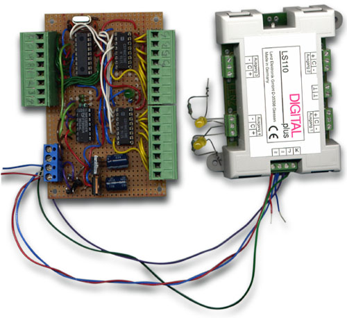
Initial test at the Helsinki clubI first assembled the unit (almost) as originally desiged to learn how it would work with Helsinki club Lenz decoders. The modifications I made to hardware were minor and in no way affected the way the system works or is originally designed: I replaced the CMOS 4515 4-to-16 (or 1-of-16) encoder with two 74HC138 3-to-8 (or 1-of-8) encoders and instead of using single transistor output stage I used two op-amps of a quad op-amp LM324 to make +/- 12 volt output as I was unsure about the operation of Lenz decoders with single sided output (the decoders have two optocouplers to sense both polarities of the DCC signal). Mike Bolton did assure me that this was, in fact, unnessesary, but... Note: Most (yet not all) accessory decoders have separate power supply connectors, so the power requirements of the DCC signal are quite low.
|
|
|
|
After I had assembled the system on a piece of Vero board I went to the club and was a bit surprised...
Something fishyI connected the encoder in place of the Lenz system and started testing. the MERG encoder has a matrix of 8 row-wires and 16 column-wires, and at the crossing of each wire is a place for a switch with a series connected diode. The turnouts are "located" in the matrix as shown below:
I started the testing! At, what I considered to be the first turnout, I got no action. The same happened to turnout 2, 3 and 4. When I tried turnout number five the turnout number one operated. I was puzzled. I then concluded that possibly the rows are not in correct order, but that too was a wrong assumption.
The problem realisedI had some e-mail exhange with the designer Mike Bolton, and he assured that the schematic was indeed correct, but Lenz idea of turnout numbering is not quite the same as others. Mike also suggested I'd get the free ShowDCC software from Tannersoft so as to double check what was in fact sent over to rails! I installed the software, and made the neccesary hardware to connect it to PC's microphone connector. Hmmm.... The turnout numbers I found at the Helsinki club were the same as those displayed by the software, but the ones that didn't work at the club (original design's turnouts 1, 2, 3 and 4) dispalyed negative turnout numbers (-3, -2, -1 and 0) Hmmm... The result was that turnouts were found as follows:
Following Mikes guidance I realized where the problem lies: The NMRA Recommended practise 9.2.1 begins with a section A: Address Partitions:
The partition for acceesory decoders is stated as:
Accessory Decoders with 9 bit addresses In this light the decoder numbering should start from address that has the first byte value of 128 (80h, '1000-0000'b). hence (if decoder addressing starts with 0):
BUT: I've been told that the NMRA DCC Working Group has agreed, that the relation between packet bit patterns and the expressed "address" need not have anything to do with each other, thus the above sample packet can equally right be expressed as TURNOUT 2 or TURNOUT 6. What I consider as open to discussion is the fact that should all command stations be capable of accessing the whole address space, if they implement accessory decoder control. Also, I'd like have some clarifiction about the contents of CV's controlling the addressing of the decoder. How can anyone describe the accessory decoders properties, if the only way is to say to which bit pattern it will response. Apparently the major NMRA-DCC compatible command system's manufacturers have choosen one or the other, and aren't so keen on explaining about their way of choosing or reasons behind their soluton, with two exceptions (NCE and ZTC). The realizationWhen I modified Mike Bolton's code I choose to use the addressing scheme similar to Lenz, where decoder addressing begins from one at 1st byte value 129 (81h). See my modified code for PIC16F84:
New development after Bankalas 2003 in Skövde, SwedenThe modified accessory encoder was tested in Skövde for a possible use of acting as a subsystem to LENZ system at Stockholm Model Railway Club local control panels: the accessory encoder was connected to a proper LENZ setup through LC100 X-pressNET DCC converter module.We encountered problems as for some reason the Lenz system didn't end sending the turnout activating DCC-commands although we had ended sending packets from this sub-system. We concluded that this could be due to only having one idle packet between turnout activating commands and that probably the LC100 requires a deactivating packet from our subsystem as we only send turnout activating packets, no loco commands at all. All in all, I modified the code and had some extensive e-mail correspondence with Lenz. The Lenz staff assured that our system should work if the sub-system is indeed sending the packets I described. It took some time until I had a chance to test the system with the updated version of the software at Helsinki club layout. Eventually it seems to work as intended. Big thank to Lenz for support, and also to Mike Bolton for exellent advice and Helsinki club for using their Lenz equipment for testing!
At Bankalas it was also agreed that the code should be modified so that the decoder addresses could be shifted without re-programming. We choose to use the last decoder's (decoder number 16 or turnouts 61..64) control terminals (turnout 61+/-, ... turnout 64 +/-) to select the starting decoder number (hence the original decoder 1 is now decoder 1 / 8 / 16 / 24 / 32 /40 / 48 / 56 or 64 depending on jumper position. If there is no jumper, only idle packets will be sent (this allows for making the control panel un-manned without disconnecting all the buttons. If the encoder would be disconnected from LC100 this would have caused a reset at LZ100!). We are still uncertain about the maximum number of turnouts LC100 can forward to master system -- the manual says "64 turnouts", but it should be 64 decoders ;).
We have made number of tests with LC100 module and still got the LZV100 to start continuously sending accessory encoder activating packets. (I even bought a Lenz SET90 of my owm to make sure I understand things correctly!) What we concluded is:
Hence the Accessory encoder designed to be used with LC100 was altered so that it will send two activating DCC-packets and two de-activating packets to make sure LC100 will notice the de-activating DCC-packets. If LC100 misses the de-activating DCC-packet from subsystem, it will not send the de-activating X-bus command to LZV, hence the Lenz system will start to send turnout activating DCC-commands forever thus burning the turnout motor and in worst case also the decoder!
|
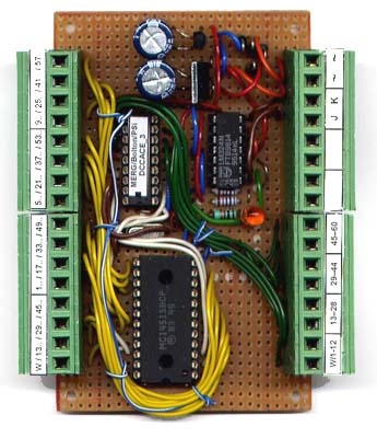 Encoder with address shift (this unit is fitted with 4514 chip instead of 2 x '138).
|
The modified schematic |
|
18529 kävijää/visitors © 1996-2026 Tapiola Parish Model Railway Club / Tapiolan seurakunnan pienoisrautatiekerho, Viimeksi päivitetty / last modified (none). Created with Notepad. Text, drawings and photos are protected by copyright laws. Technical solutions, methods and source code are public domain only for non commercial purpose. All development has been carried out during our free time, mainly funded from our own pocket and with non selfish goals, so the use of this material for profitable use (including construction for a friend aginst a fee) is forbidden without written permit from the club. The pages contain errors, so, if you use the data given, you do so at your own risk and responsibility. If you further develop material found on these pages you must put it on display without fee e.g. to a freely available web page. We expect a note about this also. Pages tested with W3C validator -- didn't look good ;) [YHTEYSTIEDOT] Älä lähetä sähköpostia! Tekstit, kuvat ja piirokset ovat tekijänoikeuslain suojaamia. Tekniset ratkaisut, menetelmät ja lähdekoodit ovat vapaasti kopioitavissa ja hyödynnettävissä ei-kaupallisissa tarkoituksissa. Kaikki kehitystyö on tehty vapaa-aikana ja pääosin henkilökohtaisilla varoilla eikä hyötymistarkoituksessa, siksi materiaalin käyttö hyötymistarkoituksiin (sisältäen kaverille rahasta rakentamisen!) on kielletty ilman kerhon kirjallista lupaa! Sivuilla esiintyy virheitä. Jos käytät sivujen tietoja hyväksesi, teet sen täysin omalla vastuullasi. Mikäli kehität sivuilla esiettyjä ajatuksia kytkentäkaavioita tai koodia edelleen, on sinun asetettava se maksutta kaikkien saataville esimerkiksi Internetiin. Odotamme vastavuoroisesti tietoa suoritetusta edelleenkehitystyöstä. Sivut testattu W3C validatorilla -- ei näyttänyt hyvältä ;) |