TaPRK
General
Projects
Shows
Excursions
Links
Yleistä
Ratoja
Projektit
Näyttelyt
Retket
Linkit
Parish/SRK
Tapiola Parish Model Railway ClubKauniainen, framework |
|---|
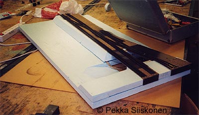
Construction of the first test module (front/back-transition module)
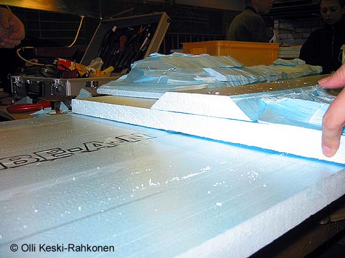
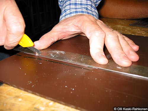
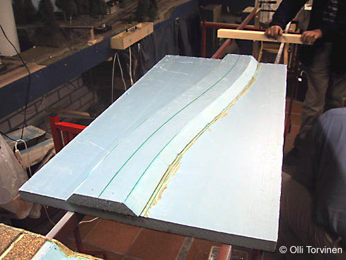
The project began by cutting about module length pieces of blue foam (Extruded polystyrene (XEPS/XPS) Trademarks: Solimate, FinnFoam)
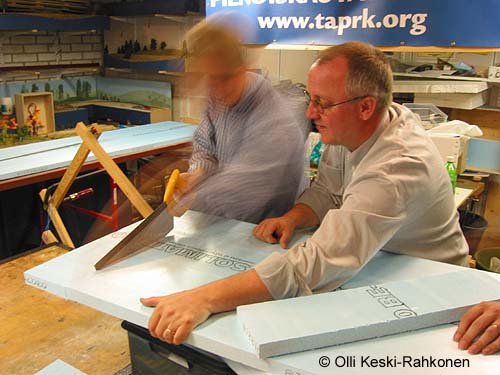
Then the hot wire cutter is set to approx 45 degrees and from the module sized sheet...
... the subroadbed (front) and scenery bases are separated (at hand and on top of plastic box...
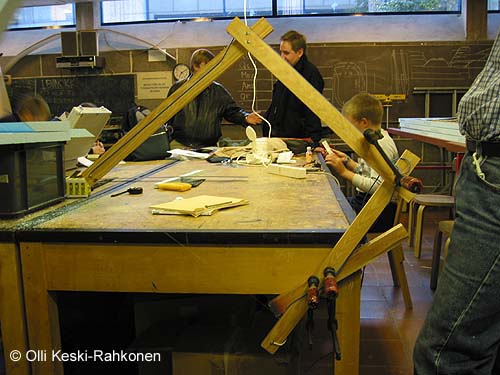
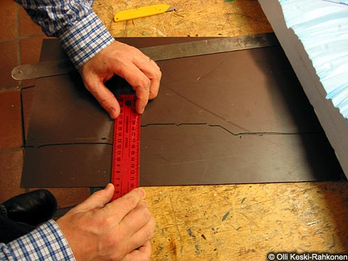
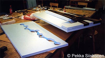
We then temporarily fitted the scenery sections to another module sized sheet and with free hand cut the scenery basic form to this lot.
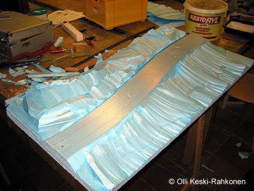
When the subroadbed is located in its original place we'll get the basic scenery with subroadbed to match ...
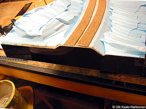
We'll then add yet another sheet of 30 mm (1 3/16" ;) sheet of foam board to get the required stiffness. There will be additional 3 mm (1/8") styrene boards at the seams to protect the end from wear and 1/8" cork (car seal material) under the track to act as roadbed...
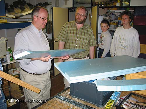
Some re-thinking: It is rather slow and tedious business to cut the scenery basic form to module width system at "one go" so I think we are in future forming the front and back pieces separately.
I think we are in fact reversing the assembly order alltogether: If we are in a hurry to get the trains running, we just separate the subroadbed and glue that in place and store the scenery pieces. We can possibly ballast the track and go on running, and later take the scenery pieces to create the desired contours we desire. If the scenery pieces are only lightly glued to base board we could even dream of snapping them away and replacing with new ones in case the scenery result is not pleasing (OK: this is again pure guessing and dreaming!)

We are now beginning to straighten the end of the module. The foam slabs were not positioned acurately enough so we now need to sand the ends flat and square.
Dusty business...
...but we get results!
We then cut profile boards from 3 mm (1/8") styrene...
... with the idea of making fully covering protective board, and by first carving the bottom slab of blue foam we could get a cavity for C-clamp to fix the modules in a row
After initial glueing we noticed that the profile board is standing upright alright, but the end bowed inside, thus leaving a nasty 3 mm (1/8in) gap at the place where the tracks should cross the module interface. The profile board was removed and gap filled and board re-glued into position.
Time to think again: This phase seemed quite time consuming. If the modules are fixed to frame tubes there should be no need to fix the modules to each other. Therefore the need for full size profile board to withstand the force of C-clamping is gone. It would be better to just use smaller pieces of styrene at the top of the joint. The most neccesary location for profile board is at the roadbed, as it supports the ballast and hinders wear.
The cork roadbed was cut to foam slab size, so we should either get it over the profile board or make "cork imitations" to profile board. As the picture shows we didn't do either this time ;(
Construction of the second transition module
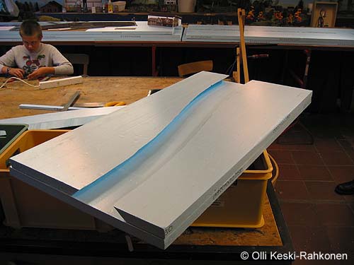
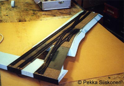
Cutting the sub-roadbed for the second transition module -- the correct one, the first one was curving the wrong way out for our Kaunianen project layout (My mistake [Pekka]!)
the sides of the sub-roadbed were sanded and the sub-roadbed glued to base...
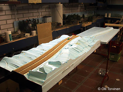
... and here we are at the moment.
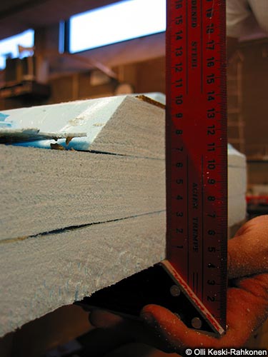
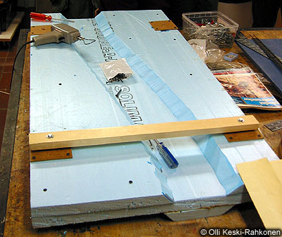
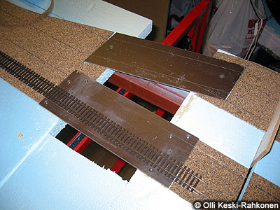
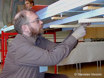
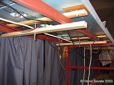
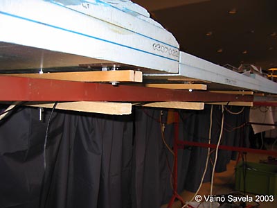
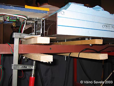
Here the 1st module from below. Clearly wisible are the 1/8 in styrene boards that were used to distribute the force of the supporting cross member to blue foam. The styrne pieces are temporaily attached with four dry wall screws, but will eventually be glued to foam. In the middle of the brown styrene boards are 1/4 in (M6) T-nuts to which the (now wooden) cross member is fitted with bolts and spacers. By adjusting the spacers the module ends, or more precisely the track ends can be fitted to uniform standard height (not agreed yet).
The strips of thin (1/8 in) rubber mat are glued under the cross members to prevent the module from slipping on top of the steel frame tubes. The rubber strips peeled off later and weren't replaced.
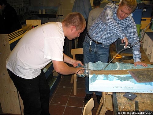
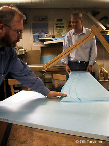
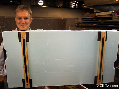
As the expression on Antti's face tells -- we are advancing! ;)
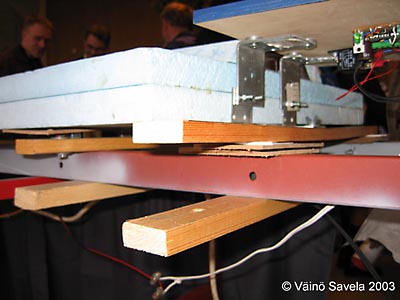
The right hand transition module's offcut scenery pieces were temporarily stored underneath the module with drywall screws so as to add support and save us from cutting yet another full size slab for this module now. This slightly reduces sagging, but we are not even near the strength of the first transition module (which has two full boards and added scenery support, all glued together).
Time to think: Our aim today was to try out if single module size board (and the sub-roadbed) would be enough to make the module rigd enough. It wasn't -- at lest not when the glue has not fully set. the cross members are placed at approx 1/5 of the length of the module to get minimum sagging if uniform weirht is applied on top of the module. With only single sheet plus the sub roadbed, pressing the module from the middle caused noticeable sagging and rised the ends of the module. In case the module were attached with rail joiners the track would be torn off from the next module. The first module has double sheets below sub-roadbed. Antti applied almost all of his body weight to the middle of the first module, but there was no noticeable sagging, except at the tubular steel frame;)
We'l check again next week after the glue has set, but propably we'll need to add another board.
Station area
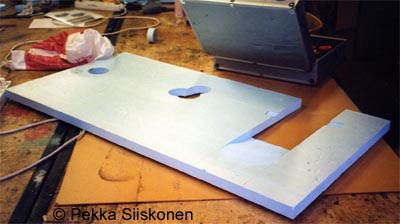
Tunnelitie underpass. The subroadbed needed to be cut away from the underpass. The whole sheet wasn't cut so as to support the other end while the glue sets.
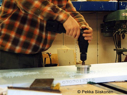
It's easy to cut wells for electrification and point motors. Note: the table is still intact! ;)
Here the topmost board (the roadbed) is cut to shape.
This is the middle board. It has wells for turnout motors.
The two topmost boards are now glued together. The station area gets into shape.
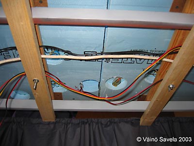
The bottom board has wells for motors and wells for track feeders. All wells were joined together by carving ducts to the top side of the bottom board.
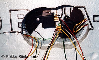
Point motors (car relays) were fastend w. wood screws to small pieces of 1/8 in styrene glued to roadbed sheet from the below
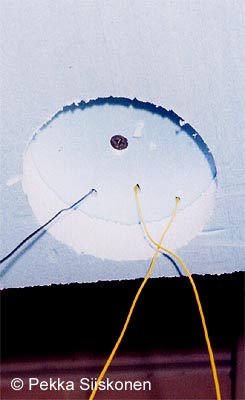
For feeders only shallow (one sheet thick) wells were made.
After the modules were lowered on top of the steel tubes, additional cross members were fitted under the steel tubes and these were clamped with long screw (threaded rod) and wingnut.
As the cross members were placed 1/5 of the module length inward, the height adjustment wasn't easy: if we reduced packing between right hand end module and cross member, the left hand end would rise. According to stress analysis it is advantageous to place support at 1/5 of the end inwards (have the distance between supports approx 3/5 of the total length of module) but the setting up now, as we have no defined standard height was not straight forward project!
The return loops built for Lahti exhibiton (2002) were connected to this design by adding another set of angle brackets to original ones that were used to attach the loops to original layout.
Time to think again
- The profile boards at ends: is the small board enough? Is the original Sallinen & Wikberg idea of foam rubber at the scenery joint a good plan?
- The height of scenery at module joint is not yet defined. For time being we'll use the plan of thinning the tob sheet (sub-roadbed) to half thickness for scenery. No provision for ditches yet!
- Wooden cross members are bending, should we cjange to steel (cost)?
- Cross members closer to ends. Will we get more sagging?
- We need a standard interface module to test the modules for height and scenery. (NB: the layout was fitted for running for the first time at the exhibition site!)
- What would be the ideal glue: glue intended for ceramic tiles is solid, would it make more solid layout? Carpet glue remains "rubbery"
Re-thinking, autum 2006
- The topmost embankment sheet of foam is completely cut away from the interface's scenery part as it is easier to "adjust" the height of the board to zero rather than somewhere in between.
- Styrene profile boards have been reduced to embankment size and the rest is of hardboard (economical solution!)
- Strips of thin sheet of rubber under cross members have been removed (well -- the glue didin't hold )
- Modules are now aligned with brass pin and fastened with small metal spring clamps. Cross members are no longer fastened to steel tubes. The fixing of cross members caused the cross members to bend and module thus rising.
- Crossmembers are attached to modules in less technical method: below the lower foam sheet small 4 in square slabs of foam are glued and cross member fitted with long 4 in wood screws
- Modules are rather light but difficult to handle as there is no solid place to grab hold of the module except the cross members. Therefore we have started to investigate framing the modules with thin plywood. More about this on separate page (not yet translated!)
7329 kävijää/visitors
© 1996-2026 Tapiola Parish Model Railway Club / Tapiolan seurakunnan pienoisrautatiekerho, Viimeksi päivitetty / last modified (none). Created with Notepad.
Text, drawings and photos are protected by copyright laws. Technical solutions, methods and source code are public domain only for non commercial purpose. All development has been carried out during our free time, mainly funded from our own pocket and with non selfish goals, so the use of this material for profitable use (including construction for a friend aginst a fee) is forbidden without written permit from the club. The pages contain errors, so, if you use the data given, you do so at your own risk and responsibility. If you further develop material found on these pages you must put it on display without fee e.g. to a freely available web page. We expect a note about this also.
Pages tested with W3C validator -- didn't look good ;)
[YHTEYSTIEDOT] Älä lähetä sähköpostia!
Tekstit, kuvat ja piirokset ovat tekijänoikeuslain suojaamia. Tekniset ratkaisut, menetelmät ja lähdekoodit ovat vapaasti kopioitavissa ja hyödynnettävissä ei-kaupallisissa tarkoituksissa. Kaikki kehitystyö on tehty vapaa-aikana ja pääosin henkilökohtaisilla varoilla eikä hyötymistarkoituksessa, siksi materiaalin käyttö hyötymistarkoituksiin (sisältäen kaverille rahasta rakentamisen!) on kielletty ilman kerhon kirjallista lupaa! Sivuilla esiintyy virheitä. Jos käytät sivujen tietoja hyväksesi, teet sen täysin omalla vastuullasi. Mikäli kehität sivuilla esiettyjä ajatuksia kytkentäkaavioita tai koodia edelleen, on sinun asetettava se maksutta kaikkien saataville esimerkiksi Internetiin. Odotamme vastavuoroisesti tietoa suoritetusta edelleenkehitystyöstä.
Sivut testattu W3C validatorilla -- ei näyttänyt hyvältä ;)