|
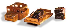
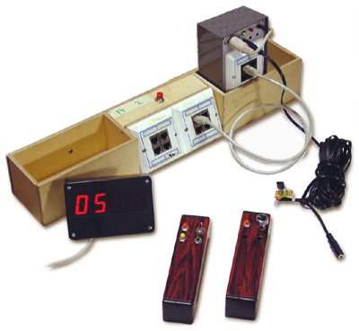
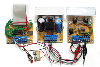
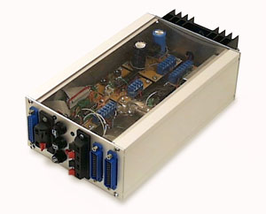
[12/10/99] Finally got the TMW boxed. The box will have a see through cover
for the curious visitors to see at Turku Exchibition 30th--31st Oct. 1999.
During fitting found some cold joints from the relay card. Perhaps the
programming will work better after re-soldering!
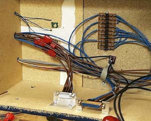
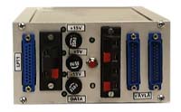
Olli installed DCC-connectors for feeding the DCC underneath the baseboards.
We used crimp connectors and 15-pin D-connectors: The 15-pin D-plug will short
all sidings etc. feeders into one, so that the power routing turnouts will be bridged.
If we want to use conventional power (no DCC), removal of the plugs will get
us back to old sysytem (power routing turnouts).
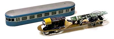
Opa (one of our members) has fitted old
Arnold decoders we have got (Thanks Lars!) to our Dm7 rail cars (Swedish Y6 models
repainted by Tomppa, another member of the club).
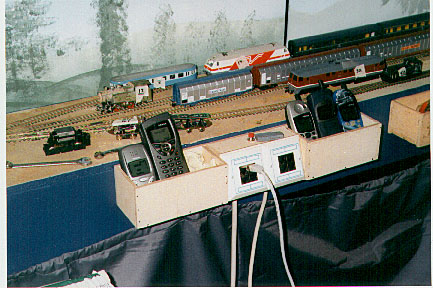
[31/10/99] Exhibited the setup at Turku exhibition. Operated the TMW for two six-hour
sessions with very little problems. The feature we were not aware of was that the
throttles are inoperative while keying in assignment commands. We also experienced
a peculiar problem due to too weak a power supply (Roco starter set transformer!):
when the internal overload cut-out started to intermittedly cut out power of the
transformer we succed in brown-out'ing the PIC in such a state that all locos switched
to dc. This kind of situation should not happen if the TMWDCC is assembled correctly
and fed directly with a power supply of correct capacity. If we would have operated the
TMWDCC with the latest version of software the emergency halt would have halted
the trains as it now also operates the relays of the relay card!
As the above incident happened at the same time as one of the operators had
his mobile phone ringing, we for a while suspected a radio frequency error, but
that was clearly ruled out as the operators did make calls to each other with the
mobile phones kept delibrately close to layout and moving trains. As the local
newspaper mentioned our stand to have the most advanced technology in the exhibition
(old 8086 PC?), the boys got an idea while I was away having a meal (they told me
this after the exhibition was colsed):
While another operator was running a loco from behind, the other operator came close
to the loco and, with his Nokia Communicator open, acted as if he was operating the
loco with it -- the first TMWDCC-WAP connection ;)
[07/11/99] In the morning I went to the Old Toy Swap (arranged by Marklin Club
of Finland) and bought two old Märklin transformers for the TMWDCC, went to
the club and retuned the Ackdetector with resistor in relay card and relying
on the LED's installed to the Ack detector output. I'm now able to read all
the decoders we have: Old Arnold, Roco, Lenz and Probst!
I also managed to install the latest (1.31) version of TMW software. All looks
great now!
[07/12/99] Helsinki MRC Xmas exhibition is behind. All in all TMWDCC operated
well. We had some problems with our emergency buttons, but those will be solved.
We are also still having a cold joint somewhere, as we are unable to connect
throttle #4 to the system (this is clearly our fault, not the system fault!)
[09/12/99] Finally found the misconnected wires of throttle#4! Noted that Emergency
halt is also inoperative during command keying. Must get the Emergency halt
to directly operate the main relay!
We still wish to get the disconnected throttle loco assignments visible on screen,
and possibility of assigning locos to disconnected throttles.
[25/04/00] The Model-Expo-2000 exhibition lasted four days, total of 30 hours of
running. TMWDCC was operational all the time, and didn't need any booting or
special attention during exhibition.
As it was impossible to change functions or see the assignments of disconnected
throttles the operators got somewhat irritated. Occasionally someone went to change
the assignments during running without warning others and this caused nuisance
(but these are features of TMWDCC).
The younger boys enjoyed the freedom of DCC too much: we had two full speed head on
collisions within five minutes! The lack of forced dicipline of the DCC in general
caused the older members to long for the old system of no DCC!
[05/07/00] Got ver 1.33 beta from Lars for trial run: Ah what Joy!
The screen now displays the loco assignments of disconnected throttles.
A faster method for typing in assignments has also being introduced
(not exactly to my liking but close enough).
We tried the "reverse DC" operation with one loco [LE103XF: CV29.2=0 and CV50.2=1].
We installed a DPDT switch to the wires between layout and booster so that with the
switch we could switch the layout into ordinary DC power pack.
The DC power pack was set into full reverse and the switch was flipped while the
loco was travelling under DCC: The loco in came into halt according to the
braking rate. We then switched back to DCC and the loco speeded at acceleration
rate set into decoder.
I understand that this feature only works with decoders built strictly according
to RP 9.2.4.
I'm being adviced that those decoders that don't follow this rule [and that are
therefore not fully NMRA-DCC compatible] are designed to give better dc operation
at low speed and pulsed power, as the processor need not take any action in dc mode.
As Tapiola presently uses solely Lenz decoders (home made decoders have not proven
to be satisfactory or worth the trouble!) we could exploit this feature.
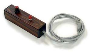
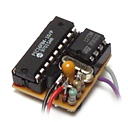
TMWDCC throttles
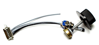
This is the first test throttle: 100k potentiometer and a switch connected
directly to D15 connector. Four throttles should be possible to be connected
to a single game controller card (speed control potentiometers in place of
joystick potentiometers and direction switches in place of fire buttons).
Maximum of 8 throttles should be possible to be connected using two game
controller cards (the other card must be modified to change the port address).
A separate bus will be fitted with RJ-45 receptacles for throttles.
[24/05/99] There is a ghost throttle #5 although only throttle #1 is connected.
This should fix when the other game port card is installed
[25/05/99] Altered the above throttle from type-A to be a type-C throttle.
Works ok. To select loco number needs some practice! Capable of switching
lights on and off from Roco receiver (five pushes of button while loco is
in motion -- fun!)
[01/06/99] Un-assigning a loco from (any) throttle and then re-assigning it
to throttle #9 (keyboard) causes the loco to halt. If throttle #9 speed is
adjusted the loco jumps to correct speed. Re-assignment to other throttles
works normally.
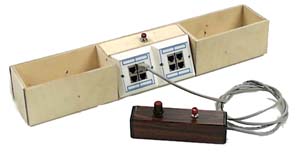
[10/08/99] Olli and Teppo (our members) got the trottle bus panels made and Lauri
(yet another member of our club) got four throttles assembled! After
some errors with soldering the cables (my mistakes!) we were able to get the
first RJ-connected throttle (cab) to be connected to throttle positions
1...4. We added an emergency halt button to RJ-socket panels just to be on the
safe side, but as the boxed TMWDCC sitill has the throttle bus connectors
not internally connected the emergency button is inoperative!!!.
[07/11/99] Unassigned trains will now surely halt at emergency too, as the latest
version (1.31) of TMW software also operates the relay after three---five
seconds after activating emergency halt, so there will be no runaway trains!
[01/12/99] Olli got the throttle bus connectors inside the TMWDCC box
connected so that we have the emergency halt buttons of the throttle panels
operating. The throttle position #4 is still unoperating, propably due to
a cold joint somewhere.
[09/12/99] Found the misconnected wires of throttle #4! Noted that Emergency
halt is also inoperative during command keying. Must get the Emergency halt
to directly operate the main relay! Throttle #9 is now with 1.32 software reset to
zero at Emegency -- great!
[22/12/99] Finally found a "matching pair" of gameport adapters: After the
boys manage to solder the missing wires of the second quad RJ-panels of the
throttle panels, we'll be able to use all eight sockets. Presently we have
a slight problem with selecting of the functions with type-C throttle, but
no doubt that will be settled soon.
[27/07/99] By changing the throttle bus capacitors from 200uF to 10uF we
got the functions working with the present joystick cards! The screen now
displays the loco assignments of disconnected throttles.
[05/07/00] Got ver 1.33 beta from Lars for trial run: Ah what Joy!
The screen now displays the loco assignments of disconnected throttles.
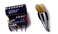
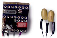
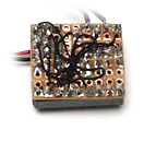
[09/04/02] First test drive with a selfmade IR throttle! IR-throttles are
under development/construction. We seem to be in a need of wireless
throttles as during exhibitions all throttle cables are usually tied
into a spagetti knot as operators move between front station and fiddle yard
at the rear of the layout.
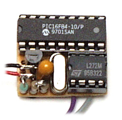
Development strted a few months ago, and first actual throttle
is complete, the second one waits for transfer from patchboard to Vero
board. I hope to have two IR-throttles in use at Model-Expo 2002 in Helsinki
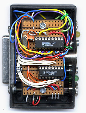
Icehall in a few weeks time. The project is based on RC5 type bit formation
but bits are shorter and message presently only consists of single
start bit, 8 bit payload and parity bit. Throttles and receiver are built
around PIC16F84 at 4 MHz, transmitters are LD271 at approx. 1 ampere and
receivers are TSOP1738 modules. This is a very barebones system, designed for
max. four throttles. The development material (not final!) may be found at
here.
[27/04/02] We have now used the first IR-throttle for two days in Model-Expo.
The throttle performs as expected. I have today assembled the second throttle
and we'll test the use of two throttles tomorrow at last day of the exhibition.
[28/04/02] Exhibition over, the system worked well, and will be developed further.
[20/08/02] Got the first proto of MkII IR-throttle! The club is about to attend
a show were we were given unlimited space, so we try to put all our modules in a
row (something like 30 metres (100ft) of modules. It would be quite unpractical
to walk to the middle of the layout just to change the loco you wish to operate,
so a mechanism was deviced that allows change of RJ-45 patch cables electronically
through the throttle. Software's now patched but not polished.
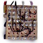
[09/09/02] Have now assembled most of the hardware to do the socket change. The vero
board is fully populated, and I need to make some piggyback chips to save space and
to avoid chaining dozens of chips on the vero board. This is no more fun...
[01/10/02] Have returned from holiday, and have come up with an idea of combining
the IR receiver and PC into a single PIC chip. During holiday tried to figure out
how to combine the DCC signal timing (needs attention every 58us) and the IR signal
timing (needs attention at unpredictable moment and then at 416us interval). The
code seems to become too complicated for me, so opted to use the TMWDCC
hardware, so that the DCC data is sent in 8 bit chunks at approx 900us rate -- yes!
[04/10/02] First successful test run of "PC-eliminator" i.e. the MkIII IR-throttle!
[08/02/03] The PC-eliminator was running during the
XX National Model Railway Days 2002 16th-17th Nov.2002
We wished a location by the wall, but instead we were placed in the middle of the hall
with walls and roof far away. We used 8 IR-receivers and got fair operation.
The Helsinki MRC's Xmas exhibition was better,
as the layout perimeter was smaller. We had two Roco cranes in operation. One of
the IR-throttles developed a fault during the first day of the show (It refused to
change address). The fault presisted allthough the processor was changed. We have now
erected the layout to the club and I hope to be able to search for the remedy the
problem of this one throttle.
[28/04/03] Last weekend was the Model-Expo show in the old Helsinki Ice Hall. We operated
the three day show with PC-Eliminator and TMWDCC hardware. I havent yet sent the faulty
Lenz LE103FX decoders to Lenz for repair (need the extra capacitor next to zener), so
we were guaranteed to have some runaway trains. the above mentioned throttle not changing
address was fixed (adjusted the speed pot trimmer). It seems that the system is forgetting the
addresses of locos or something as we quite often had to reset the locos by keeping
them off the metals (tilt) for a few seconds. I plan to modify the PC-eliminator
code so that it will display the addresses of cabs in sequence if nothing more
pressing is to be displayed so as to make sure the addresses aren't lost during running!
[24/11/03] I have now upgraded the PC-eliminator software so that is not allowing loco
(address) capture in case the previous owner has the speed in non-zero position (diplay
shows "Err!").
Apparently this is not enough, as we are still experiencing the need to re-press the address
selector due to throttle loosing control. I have now included a double packet check into
software, but commented it out as it seemed too slow (ther must be two identical commands from
individual throttle before the action is taken). I'll investigate further, probably it should
be selective so that only direction change and address change would be double checked.
I also realized a design fault: The speed pot is read so that the greater the resistance
the faster the loco goes. As the tracks of pots get worn out we get (or got!) an uncontrollable
situation. Not nice!
Antti has some rotary encoders, and I'm going to look into possibility of replacing the pots
with encoders. Also, I think we'll need button type throttles as well, as those are excellent
in trying to get the youngsters into driving more carefully.
The display now shows in sequence the address, speed and functions settings of throttles in case
no-one is sending any IR-packets. As the amount of packets during operating session is so great
the display is of no use during ordinary running. I think that the display should in fact only
show the sequential data and not try to display everything (the eye cannot catch individual
commands from flashing display).
See Tillorps
Mekaniska Werkstad for complete description of TMWDCC by Lars Lundgren.
|
![Schematic diagram of modified Probst decoder [4K]](./../../../img/project/dcc/probst_1.gif)
![Schematic diagram of modified Probst decoder Mk II [4K]](./../../../img/project/dcc/probst_2.gif)